R200 - токозадающий. Вместе с ним - только коммутация других резисторов тумблерами/кнопками.
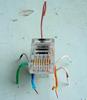
Что на 6-ногой детальке написано ? Может есть вариант слаботочного диммирования..
 |
 |
 |
помогите с драйвером
Re: помогите с драйвером
![]() ivdor » 15 июл 2015, 20:41
ivdor » 15 июл 2015, 20:41
Оно и не что-либо как и не как-либо что. А что касательно относительно - то безусловно. Оно и не надо было бы, но доведись такое дело - вот я вам и пожалуйста. Я все.
PS: используйте вышеприведенную информацию на свой страх и риск..
PS: используйте вышеприведенную информацию на свой страх и риск..
-
ivdor - Scio me nihil scire

- Сообщений: 3851
- Зарегистрирован: 29 июл 2011, 00:49
- Откуда: Псков, СЗФО.
- Благодарил (а): 24 раз.
- Поблагодарили: 270 раз.
Re: помогите с драйвером
![]() jml 2999 » 15 июл 2015, 21:33
jml 2999 » 15 июл 2015, 21:33
ivdor писал(а):Что на 6-ногой детальке написано ?
LEDA
1410
- jml 2999
- Фонарик

- Сообщений: 12
- Зарегистрирован: 04 июл 2015, 13:48
- Благодарил (а): 7 раз.
- Поблагодарили: 0 раз.
Re: помогите с драйвером
![]() Invisible_Light » 16 июл 2015, 00:42
Invisible_Light » 16 июл 2015, 00:42
Примерно похожий http://beriled.biz/product_143.html драйвер. Дана ориентировочная таблица замены токовых резисторов : исходный R20 отпаять (греть одновременно с двух торцов, можно двумя небольшими паяльниками или одним с широким жалом).
Припаять 3шт. по 1_Ом в параллель друг на друга. Получится 0,33_Ом. К этому резистору подключать тумблером с малым сопротивлением ещё примерно 0,5-0,6_Ом для увеличения тока.
Припаять 3шт. по 1_Ом в параллель друг на друга. Получится 0,33_Ом. К этому резистору подключать тумблером с малым сопротивлением ещё примерно 0,5-0,6_Ом для увеличения тока.
- За это сообщение автора Invisible_Light поблагодарил:
- jml 2999 (16 июл 2015, 08:47)
- Invisible_Light
- Scio me nihil scire
- Сообщений: 6014
- Зарегистрирован: 17 июн 2012, 01:53
- Откуда: Киров
- Благодарил (а): 13 раз.
- Поблагодарили: 968 раз.
Re: помогите с драйвером
![]() mnashe » 16 июл 2015, 02:40
mnashe » 16 июл 2015, 02:40
Я наконец померил свой — оказалось 50 мкм (включая клей, но не включая подложку).большой писал(а):Скотч алюминиевый бывает до 200микрон, самый ходовой 45микрон

Медный скотч оказался чуть толще — 65 мкм.
А ещё у меня есть медная фольга (без клея) — 150 мкм.
Вот это уже получше.
Я её, в частности, использую, чтобы тепло от микросхемы в драйвере и т.п. или от светодиода вывести на другую сторону платы. Развожу плату так, чтобы греющийся элемент был с краю, напаиваю под него на плату полоску фольги и заворачиваю фольгу на другую сторону.
Если полоска больше пяти квадратных сантиметров, то паять к ней паяльной станцией у меня не получается, приходится брать паяльник с жалом потолще.
-

mnashe - Светильник

- Сообщений: 93
- Зарегистрирован: 08 май 2012, 18:48
- Откуда: Кармиэль
- Благодарил (а): 6 раз.
- Поблагодарили: 16 раз.
Re: помогите с драйвером
![]() mnashe » 16 июл 2015, 02:53
mnashe » 16 июл 2015, 02:53
LEDA xxxx (смысл номера я так и не понял) — так обозначается очень распространённая в китайских фонариках микросхема драйвера QX9920.jml 2999 писал(а):LEDAivdor писал(а):Что на 6-ногой детальке написано ?
1410
К сожалению, информации по ней очень мало, datasheet коротенький, да и тот наполовину на китайском, пришлось гуглятором переводить (я себе её купил, она достаточно дешёвая и я не знаю ни одной альтернативы).
Вот сам datasheet:
 QX9920.PDF
- (182.82 KIB) Скачиваний: 1797
а вот гуглоперевод китайской части:
Preliminary
Outline
QX9920 is a high efficiency, stable and reliable high power LED lamp driver control IC, built-in high-precision comparator, off-time control circuit, the current driving control circuit, particularly suitable for high power, high brightness multiple LED strings constant-current drive.
QX9920 uses a fixed off-time control work, the operating frequency up to 2.5MHz, allows external inductors and filter capacitors, size reduction, efficiency.
In addition PWM signal EN pin adjustable LED light brightness.
By adjusting the external resistor to control high-brightness LED Lamp drive current, the LED lamp brightness to achieve the desired constant light level, through the high brightness LED lamp current from a few milliamperes to 1 Ampere.
• Property programmable LED drive current programmed range of 10mA to 1A
• High efficiency: 90%
• Input voltage range: 2.5V ~ 24V
• Operating frequency is adjustable: 500KHz ~ 2.5MHz
• driven LED lights feature strong:
LED light string can be from 1 to hundreds of high-brightness LED lights
• PWM adjustable brightness: adjust LED lamp brightness through EN pin,
• SOT-23-6 package
Applications
• 12V / 24V car power LED lights cup
• RGB large display screen high-brightness LED lights
• flat panel display LED backlight
• traffic warning LED lights
• common constant current source
Internal Block Diagram
LED driver control IC QX9920
Circuit work
QX9920 uses peak current control mode and fixed off-time detection circuit in the switch turns on and off the two states:
1. Conducting state: see block circuit diagram, MOS switch is in an ON state, the input voltage Vin through the inductor L, LEDs, MOS switch, the inductor current sense resistor Rcs charges inductor L. charging current increases with time, when the inductor current reaches 250mV / Rcs, QX9920 comparator output high and triggers the RS flip-flop thereby turning off the MOS switch.
2. Off state: MOS switch is in the off state, the inductor through the loop by the LEDs, diode D and inductor L itself composed of LEDs discharge, MOS switch after a fixed time Toff, turns back to the conduction state and repeatedly turns on and off course.
Fixed off-time Toff can be calculated from Roff and Coff setting:
Roff•100KOhm
Toff = ──────── • 0.51 • (Coff+12pF)
Roff+100KOhm
If you do not add Roff and Coff, QX9920 inside the off-time is set to:
Toff=612ns
LEDs current is set by the Rcs:
250mV
Iled = ───
Rcs
-
mnashe - Светильник
- Сообщений: 93
- Зарегистрирован: 08 май 2012, 18:48
- Откуда: Кармиэль
- Благодарил (а): 6 раз.
- Поблагодарили: 16 раз.
Re: помогите с драйвером
![]() ivdor » 16 июл 2015, 03:28
ivdor » 16 июл 2015, 03:28
leda xxxx - дата производства и партия.
Вот английский даташит - немного другие формулы и нет речи про ШИМ. Рулиться-то будет, но вот частота шим-диммирования под вопросом.
http://www.dianyuan.com/upload/communit ... -56499.pdf
копия (на всякий случай) https://yadi.sk/i/jeNfuKZ-htiqy
Вот английский даташит - немного другие формулы и нет речи про ШИМ. Рулиться-то будет, но вот частота шим-диммирования под вопросом.
http://www.dianyuan.com/upload/communit ... -56499.pdf
копия (на всякий случай) https://yadi.sk/i/jeNfuKZ-htiqy
Оно и не что-либо как и не как-либо что. А что касательно относительно - то безусловно. Оно и не надо было бы, но доведись такое дело - вот я вам и пожалуйста. Я все.
PS: используйте вышеприведенную информацию на свой страх и риск..
PS: используйте вышеприведенную информацию на свой страх и риск..
-
ivdor - Scio me nihil scire
- Сообщений: 3851
- Зарегистрирован: 29 июл 2011, 00:49
- Откуда: Псков, СЗФО.
- Благодарил (а): 24 раз.
- Поблагодарили: 270 раз.
Re: помогите с драйвером
![]() mnashe » 16 июл 2015, 11:18
mnashe » 16 июл 2015, 11:18
Кстати, натыкался на эту странность в datasheet’е на другую серию китайских микросхем — XL6003..XL6006. Там тоже есть вход включения-выключения (обозначен EN), но почему-то в диммируемом варианте схемы в typical application circuits он не используется вообще никак, а вместо этого ШИМ-сигнал подаётся (через диод) на вход обратной связи (предназначенный для токосъёмного резистора). Зачем это извращение, я так и не понял. Потестировал собранный драйвер ШИМ-сигналом на входе EN — работает прекрасно. Я, правда, большие частоты не испытывал, но не меньше 200 Гц вроде было.ivdor писал(а):и нет речи про ШИМ. Рулиться-то будет, но вот частота шим-диммирования под вопросом.
-
mnashe - Светильник
- Сообщений: 93
- Зарегистрирован: 08 май 2012, 18:48
- Откуда: Кармиэль
- Благодарил (а): 6 раз.
- Поблагодарили: 16 раз.
Re: помогите с драйвером
![]() ivdor » 17 июл 2015, 03:39
ivdor » 17 июл 2015, 03:39
Разница скорее всего в том, что в xl600_ сигнал с EN проходит через кусок плавного запуска и при какой-то частоте (не нашел время софт-старта в даташитах) микруха может не успевать включаться.
То же самое и с другими микросхемами - если нет отдельной ноги для диммирования, то это будет именно ШИМ-регулирование. Которое хоть и сгладится за счет индуктивности и емкости, но ток все равно не будет на одном уровне. Тогда как отдельный вход будет сглаживать ШИМ и влиять уже на внутреннее напряжение сигнала ОС.
То же самое и с другими микросхемами - если нет отдельной ноги для диммирования, то это будет именно ШИМ-регулирование. Которое хоть и сгладится за счет индуктивности и емкости, но ток все равно не будет на одном уровне. Тогда как отдельный вход будет сглаживать ШИМ и влиять уже на внутреннее напряжение сигнала ОС.
Оно и не что-либо как и не как-либо что. А что касательно относительно - то безусловно. Оно и не надо было бы, но доведись такое дело - вот я вам и пожалуйста. Я все.
PS: используйте вышеприведенную информацию на свой страх и риск..
PS: используйте вышеприведенную информацию на свой страх и риск..
-
ivdor - Scio me nihil scire
- Сообщений: 3851
- Зарегистрирован: 29 июл 2011, 00:49
- Откуда: Псков, СЗФО.
- Благодарил (а): 24 раз.
- Поблагодарили: 270 раз.
Вернуться в Питание и подключение светодиодов
Кто сейчас на форуме
Зарегистрированные пользователи: Bing [Bot], Светочъ, Google [Bot], Kodmig, mailru, Majestic-12 [Bot], Василий177, Яндексбот